NCERT Solutions for Class 12 Physics Chapter 6 - Electromagnetic Induction

NCERT Solutions for Class 12 Physics Chapter 6 Free PDF Download
Please Click on Free PDF Download link to Download the NCERT Solutions for Class 12 Physics Chapter 6 Electromagnetic Induction
1. Predict the direction of induced current in the situation described by the following figures:
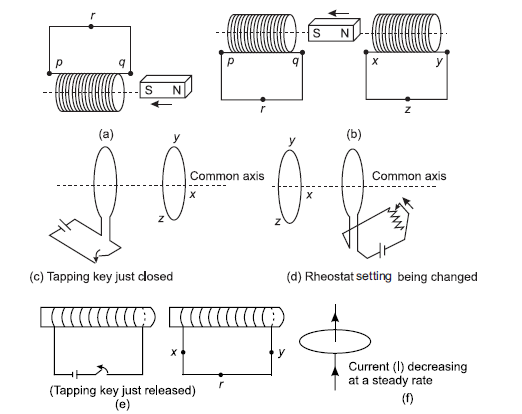
Sol. (a) As, south pole is moving towards the coil, so according to Lenz’s law this end becomes S-pole. Hence, the direction of current is clockwise and the current flows from p to q.
(b) In coil p-q, at end q, S-pole is moving towards end q, so it behaves like a south pole. The direction of current is clockwise, i.e., from p to q. North pole is moving away so this end will behave like South pole. In coil x-y, S-pole is induced.
(c) Since the tapping key is just closed, the current in coil increases. So, the magnetic flux and field increases. Using right hand grip rule, the direction of magnetic field is leftwards. Thus, the direction of induced current in the neighbouring coil is such that it try to decrease the field, thus the direction of field in the neighbouring coil should be rightwards, i.e. according to Maxwell’s right hand rule the direction of induced current is anticlockwise, i.e. xyz.
(d) On changing the rheostat setting, the current is changed. The direction of field due to the coil is leftwards according to Maxwell’s right hand grip rule. The direction of induced current in the left coil is such that the magnetic field produced by it in rightwards, thus the direction of current in left coil is anticlockwise i.e., from zyx.
(e) When key is just released, the current which is flowing anticlockwise goes on decreasing. Thus, the induced current developed in such a sense the magnetic field due to left coil increases. So, the magnetic field due to the right coil should also towards right and hence the induced current is in anticlowise, i.e. x to yx-direction.
(f) The magnetic field lines due to the current carrying wire are in the plane of the loop. Hence, no induced current is produced in the loop because no flux lines crosses the area of loop.
2. Use Lenz’s law to determine the direction of induced current in the situations described by figure.
(a) A wire of irregular shape turning into a circular shape.
(b) A circular loop being
deformed into a narrow straight wire.
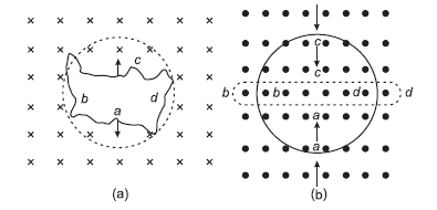
Sol. (a) Here, the direction of magnetic field is normally inwards to the plane of paper. If a wire of irregular shape deform into a circular shape due to which area increases so that the magnetic flux increases. Now, the induced current is produced in a direction such that it decreases. The magnetic field [i.e., The current will flow in such a direction so that the wire forming the loop is pulled inward in all directions.] i.e. current is in flowing anticlockwise direction, i.e., adcba.
(b) When a circular loop turn into a narrow straight wire, the magnetic flux linked with it also decreases. The current induced due to change in flux will flow in such a direction that it will oppose the decrease in magnetic flux so it will flow anticlockwise, direction i.e., along a’d’c’b’a’, due to which the magnetic field produced will be out of the plane of paper.
3. A long solenoid with 15 turns per cm has a small loop of area 2.0 cm2 placed inside the solenoid normal to its axis. If the current carried by the solenoid changes steadily from 2.0 A to 4.0A in 0.1 s, what is the induced emf in the loop while the current is changing?
$$\text{Sol. Change in current}\space\frac{\text{dI}}{\text{dt}}=\frac{4-2}{0.1}=\frac{2}{0.1}=\text{20A/s}$$
According to Faraday’s law,
$$\text{e}=\frac{d\phi}{dt}=\frac{d}{dt}(\text{BA})\qquad(\because\phi=\text{BA})\\\text{Induced emf.}\\\text{or}\space e=\text{A}\frac{\text{dB}}{dt}=\text{A}\frac{d}{dt}(\mu_{0}\text{nI})$$
(∵ Magnetic field inside the solenoid B = µ0nI)
$$\text{or}\space e=\text{A}\mu_{0}n\frac{\text{dI}}{\text{dt}}$$
e = 2 × 10–4 × 4×3.14 × 10–7 ×1500 × 20
(∵ m0 = 4p × 10–7)
e = 7.5 × 10⁶ V
Thus, the induced emf in the loop is 7.5 × 10⁶ V.
4. A rectangular wire loop of sides 8 cm and 2 cm with a small cut is moving out of a region of uniform magnetic field of magnitude 0.3T directed normal to the loop. What is the emf developed across the cut if the velocity of the loop is 1 cm/s in a direction normal to the (a) longer side, (b) shorter side of the loop? For how long does the induced voltage last in each case?
Sol. (a) When velocity is normal to the longer side
(length l = 8 cm = 8 × 10⁻² m)
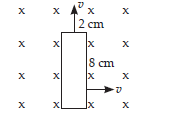
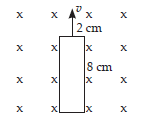
In this case, the new emf
e = Blv = 0.3 × 2 × 10–2 × 0.01
e = 0.6 × 10⁻⁴V
$$\text{Time}=\frac{\text{Longerside(length)}}{\text{Velocity}}=\frac{8×10^{\normalsize-2}}{0.01}$$
t = 8s
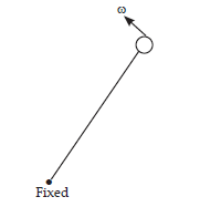
5. A 1.0m long metallic rod is rotated with an angular frequency of 400 rad/s about an axis normal to the rod passing through its one end. The other end of the rod is in contact with a circular metallic ring. A constant and uniform magnetic field of 0.5T parallel to the axis exists everywhere. Calculate the emf developed between the centre and the ring.
Sol. Length of metallic rod, l = 1 m
Angular frequency, w = 400 rad/s
Magnetic field, B = 0.5T
The linear velocity of fixed end is 0.
The linear velocity of other end = lw (∵ v = rω)
Average linear velocity
$$\text{v}=\frac{0+l\omega}{2}=\frac{l\omega}{2}\space\text{...(i)}$$
Applying formula of motional emf,
$$\text{e}=\text{Bvl}=\frac{\text{Bl}\omega}{2}.l\space[\text{from Eq. (i)}]\\\text{e}=\frac{0.5×1×400×1}{2}=100\text{V}$$
Thus, the emf developed between the centre and ring is 100V.
6. A circular coil of radius 8.0 cm and 20 turns is rotated about its vertical diameter with an angular speed of 50 rad/s in a uniform horizontal magnetic field of magnitude 3.0 × 10⁻² T. Obtain the maximum and average emf induced in the coil. If the coil forms a closed loop of resistance 10W, calculate the maximum value of current in the coil. Calculate the average power loss due to Joule heating. Where does this power come from?
Sol. Induced emf in the coil e = NBAω sin ωt
For maximum emf, sin ωt = 1
∴ Maximum emf e0 = NBAω
= 20 × 3 × 10–2 × 3.14(0.08)2 × 50 = 0.603V
$$\text{Maximum current in the coil I}_{0}=\frac{e_{0}}{\text{R}}\\=\frac{0.603}{10}=0.0603\text{A}$$
Average induced emf
$$e_{av}=\frac{1}{\text{T}}\int^{2\pi}_{0}\text{e dt}\\=\frac{1}{\text{T}}\int^{2\pi}_{0}\text{NBA} \omega\space\text{sin}\omega t\space dt\\=\frac{1}{\text{T}}.\text{NAB}\omega\bigg[\frac{\text{cos} \omega t}{\omega}\bigg]^{2\pi}_{0}\\\frac{\text{NBA}}{\text{T}}.[\text{cos}2\pi-\text{cos} 0\degree]\\e_{av}=\frac{\text{NBA}}{\text{T}}.[1-1]=0$$
Average emf for full cycle, eav = 0
Average power loss due to heating
$$=\frac{\text{E}_{0}\text{I}_{0}}{2}\\=\frac{0.603 × 0.0603}{2}=0.018\text{W}$$
The source of power dissipated as heat in the coil is the external rotar and current induced in the coil causes a torque that opposes the rotation of the coil. Thus, the external agent rotar counter this torque to keep the coil rotating uniformly.
7. A horizontal straight wire 10 m long extending from east to west is falling with a speed of 5.0 m/s, at right angles to the horizontal component of the earth’s magnetic field, 0.30 × 10⁻⁴ Wb/m2.
(a) What is the instantaneous value of the emf induced in the wire?
(b) What is the direction of the emf?
(c) Which end of the wire is at the higher electrical potential?
Sol. Given, velocity of wire = 5 m/s
Magnetic field B = 0.30 × 10⁻⁴ Wb/m2
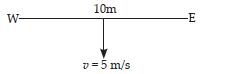
Length of wire l = 10 m
(a) Induced emf e = Blv sin θ
∴ sin θ = 1
θ = 90°
= 0·3 × 10–4 × 10 × 5
= 1·5 × 10–3V
(b) According to the Fleming’s right hand rule, the force is downward, then the direction of induced emf will be from west to east.
(c) As the direction of induced emf is from west to east, the west end of the wire is at higher potential. (∵ Current always flows from higher potential to lower potential.)
8. Current in a circuit falls from 5.0A to 0.0A in 0.1s. If an average emf of 200V induced, give an estimate of the self-inductance of the circuit.
Sol. Change in current, dI = 5 – 0 = 5A
Time taken in current change dt = 0.1s
Induced average emf eav = 200V
$$\text{Induced emf in the circuit e = L}\frac{dI}{dt}\\200=\text{L}\bigg(\frac{5}{0.1}\bigg)\text{or L}=\frac{200}{50}=4\text{H}$$
9. A pair of adjacent coils has a mutual inductance of 1.5H. If the current in one coil changes from 0 to 20A in 0.5s, what is the change of flux linkage with the other coil?
Sol. Given, mutual inductance of coil
M = 1.5 H
Current change in coil dI = 20 – 0 = 20A
$$\text{Induced emf in the coil e = M}\frac{dI}{dt}=\frac{d\phi}{dt}$$
or dΦ = M.dI = 1.5 × 20
dΦ = 30 Wb
Thus, the change of flux linkage with other coil is 30 Wb.
10. A jet plane is travelling towards west at a speed of 1800 km/h. What is the voltage difference developed between the ends of the wing having a span of 25m, if the earth’s magnetic field at the location has a magnitude of 5 × 10⁻⁴ T and the dip angle is 30°.
Sol. Speed of jet plane v = 1800 km/h
$$=1800×\frac{5}{18}=500\space\text{m/s}$$
l = Distance between the ends of the wings = 25 m
The magnitude of magnetic field B = 5 × 10⁻⁴T
Angle of dip δ = 30°
Use the formula of motional emf,
e = Bvvl
e = B sin d.vl
e = 5 × 10⁻⁴ sin 30° × 500 × 25 = 3.1V
Thus, the voltage difference between the ends is 3.1V.
Share page on
NCERT Solutions Class 12 Physics
- Chapter 1 Electric Charges and Fields
- Chapter 2 Electrostatic Potential and Capacitance
- Chapter 3 Current Electricity
- Chapter 4 Moving Charges and Magnetism
- Chapter 5 Magnetism and Matter
- Chapter 6 Electromagnetic Induction
- Chapter 7 Alternating Current
- Chapter 8 Electromagnetic Waves
- Chapter 9 Ray Optics and Optical Instruments
- Chapter 10 Wave Optics
- Chapter 11 Dual Nature of Radiation and Matter
- Chapter 12 Atoms
- Chapter 13 Nuclei
- Chapter 14 Semiconductor Electronics
- Chapter 15 Communication System
CBSE CLASS 12 NCERT SOLUTIONS
- NCERT Solutions Class 12 English Core
- NCERT Solutions Class 12 Physics
- NCERT Solutions Class 12 Chemistry
- NCERT Solutions Class 12 Biology
- NCERT Solutions Class 12 Business Studies
- NCERT Solutions Class 12 Mathematics
- NCERT Solutions Class 12 Accountancy
- NCERT Solutions Class 12 Economics
- NCERT Solutions Class 12 Geography
- NCERT Solutions Class 12 History
- NCERT Solutions Class 12 Political Science
CBSE CLASS 12 SYLLABUS
- CBSE Class 12 English core Syllabus
- CBSE Class 12 Mathematics Syllabus
- CBSE Class 12 Physics Syllabus
- CBSE Class 12 Chemistry Syllabus
- CBSE Class 12 Biology Syllabus
- CBSE Class 12 Accountancy Syllabus
- CBSE Class 12 Business Studies Syllabus
- CBSE Class 12 Economics Syllabus
- CBSE Class 12 History Syllabus
- CBSE Class 12 Geography Syllabus
- CBSE Class 12 Political science Syllabus
- CBSE Class 12 Sociology Syllabus
- CBSE Class 12 Psychology Syllabus
- CBSE Class 12 Physical education Syllabus
- CBSE Class 12 Applied mathematics Syllabus
- CBSE Class 12 History of Indian Arts Syllabus
- CBSE Class 12 Entrepreneurship Syllabus
CBSE CLASS 12 Notes
- CBSE Class 12 Physics Notes
- CBSE Class 12 Chemistry Notes
- CBSE Class 12 Biology Notes
- CBSE Class 12 Maths Notes
- CBSE Class 12 Accountancy Notes
- CBSE Class 12 Business Studies Notes
- CBSE Class 12 Economics Notes
- CBSE Class 12 History Notes
- CBSE Class 12 Geography Notes
- CBSE Class 12 Political Science Notes
CBSE CLASS 12 BOOKS